
Aerospace manufacturing is one of the most demanding industries in the world. Every component that goes into an aircraft, satellite, or defence system must meet exact dimensional tolerances, survive extreme operating conditions, and carry a verifiable identity that follows it through its entire service life. There is no margin for error — and the manufacturing tools used to produce these components must reflect that reality.
This blog explores why laser machines for aerospace manufacturing have become a non-negotiable part of modern aerospace production. It is written for procurement managers, production engineers, and operations leaders at aerospace manufacturers who are either evaluating laser technology for the first time or looking to understand whether their current laser processing capability is aligned with what the industry now demands.
We begin by explaining why conventional manufacturing methods — CNC routing, mechanical punching, TIG welding, and ink-based marking — fall short when applied to the materials, tolerances, and regulatory requirements that define aerospace production today. We then walk through each of the three core laser processes — cutting, welding, and marking — explaining the specific problems each one solves and the applications where it delivers the most value.
Throughout the blog, you will find links to in-depth supporting articles on topics including sandwiched aluminium sheet cutting, tube laser cutting for aerospace frames, composite material processing, laser welding quality certification, and traceability marking — giving you a clear path to go deeper on any topic most relevant to your production environment.
We also introduce SLTL’s range of laser cutting, welding, and marking machines — from the high-power Infinity F1 and advanced Future X cutting systems, to the Nova and Hertz welding machines, to SPM marking solutions for 2D and 3D aerospace identification jobs — and explain how each maps to specific aerospace manufacturing requirements.
By the end of this blog, you will have a clear picture of where laser processing adds the most value in aerospace manufacturing, what machine capabilities to look for, and how to take the next step in evaluating the right solution for your facility.
Why Aerospace Manufacturers Need High-Accuracy Laser Processing
When an aircraft takes off, every single component on board has been manufactured, inspected, certified, and traced through a chain of documentation that spans suppliers, sub-suppliers, and regulatory authorities across multiple countries. A single component that does not meet dimensional tolerance, a weld that contains a microscopic void, or a part marking that becomes unreadable after a paint cycle — any one of these can delay a programme, trigger a fleet-wide airworthiness directive, or in the worst case, contribute to a catastrophic failure.
That is the operating reality of aerospace manufacturing. And it is why the choice of manufacturing technology — the machines on the shop floor — carries consequences that go far beyond cost-per-part.
Over the last two decades, laser machines for aerospace manufacturing have moved from a niche solution to a production-critical technology. Laser cutting machines, laser welding machines, and laser marking machines are now standard equipment in Tier 1 and Tier 2 aerospace supply chains worldwide. The reason is not simply that lasers are more precise than conventional alternatives — though they are. It is that lasers offer a combination of precision, repeatability, material compatibility, and traceability integration that the specific demands of aerospace manufacturing require, and that no other single technology family can match.
This article explains why. It covers the limitations of conventional manufacturing methods for aerospace applications, the specific role of each laser process in solving those limitations, and the machine capabilities that define a genuine aerospace-grade laser processing solution.
Why Conventional Manufacturing Methods Fall Short in Aerospace
The Material Challenge
Aerospace components are manufactured from a material mix unlike any other industry. In a single airframe assembly programme, you might encounter 7000-series aluminium alloys for structural panels, titanium 6Al-4V for fastener bosses and fittings, Inconel for engine-adjacent components, carbon fibre reinforced polymer (CFRP) for control surfaces and fairings, aramid-based composites (Kevlar) for ballistic and interior panels, and adhesive-bonded sandwiched aluminium panels for flooring and bulkhead structures.
Each of these materials has distinct mechanical, thermal, and chemical properties that determine how it can and cannot be processed. What works well for one material — high cutting forces, elevated heat input, solvent-based marking — can cause catastrophic damage to another.
The Problem with Contact-Based Cutting
CNC routing and mechanical punching rely on direct physical contact between a cutting tool and the workpiece. In conventional sheet metal fabrication, this is entirely appropriate. In aerospace, it introduces a set of problems that are difficult to resolve without changing the process entirely.
Tool wear is the first issue. As a cutter wears, its geometry changes subtly — and in aerospace, subtle dimensional changes are not acceptable. A worn cutter that produces parts 0.15 mm outside nominal on a structural bracket represents a non-conformance that must be scrapped or subjected to costly rework disposition. Managing tool wear means frequent replacement, increased tooling cost, and ongoing dimensional monitoring to catch drift before it propagates through a batch.
Mechanical stress at the cut zone is the second issue. For composite materials, the lateral forces of a rotating cutter cause fibre pull-out at the cut edge, interlaminar delamination, and matrix cracking — all of which degrade the structural performance of the finished part and create a reject that cannot be reworked. For thin-section metallic components, contact forces cause distortion and springback that defeat the purpose of close-tolerance cutting.
Heat buildup at the tool tip causes matrix burning in composites and workhardening in titanium alloys. Secondary deburring operations add time and labour cost to every metallic part. And for sandwiched aluminium panels — where the honeycomb or foam core has very different mechanical properties from the aluminium face skins — contact cutting risks crushing the core or separating the bond between skin and core.
If you are currently running CNC routing for sheet and composite work and evaluating whether laser is the right alternative, our detailed process comparison — Laser Cutting vs CNC Routing for Aerospace Sheet and Composite Parts — walks through both technologies across every major aerospace material family to help you make that decision with objective data.
The Composite Material Problem
Of all the material challenges in aerospace cutting, composite materials are the most demanding. Multi-directional fibre lay-ups, adhesive-bonded panel systems, and hybrid metal-composite assemblies all share one characteristic: any cutting method that applies lateral force to the material risks disrupting the structural integrity of the part.
Contactless processing — laser cutting — eliminates this problem entirely. A laser beam interacts with the material through focused photonic energy alone. There is no lateral force, no tool pressure, no mechanical contact whatsoever. The beam vaporises or ablates material at the cut zone and moves on, leaving an edge that is clean, consistent, and free from the delamination and fibre pull-out that characterise contact cutting of composites.
For manufacturers working with CFRP, aramid composites, or hybrid sandwich structures, our in-depth article on Why Composite Material Cutting Needs Contactless Laser Technology explains the failure mechanisms of contact cutting in composites and the specific laser parameters that deliver clean, low-HAZ edges in these materials.
The Traceability and Marking Problem
Aerospace components must carry permanent, tamper-resistant identification. AS9100, EASA Part 21, FAA regulations, and customer-specific requirements all mandate that every flight-critical component be traceable back to its manufacturing batch, material certificate, inspection records, and design approval. Ink-based printing fades, adhesive labels peel, and mechanical stamping introduces surface stress that is unacceptable on fatigue-critical parts. None of these methods meet the permanence and tamper-resistance that aerospace traceability requires.
Laser marking is the solution the industry has converged on — and for good reason. A laser mark on a metal or composite part is permanent, flush with the surface, readable under all lighting conditions, and cannot be removed or altered without physically damaging the component in a way that inspection would immediately identify.
Laser Cutting for Aerospace: The Right Process for Every Material
Sandwiched Aluminium Sheet Cutting
Sandwiched aluminium panels — aluminium face skins bonded to a honeycomb or foam core — are used extensively in aerospace flooring, bulkheads, fuselage linings, and fairings. Cutting these panels presents a unique challenge because the laser parameters that work for the aluminium face skins are different from those needed for the core material. A single pass must process both without burning the core or losing the bond between skin and core.
Modern high-brightness fibre laser cutting machines achieve this through precise control of laser power, pulse parameters, and assist gas strategy. The result is a cut edge that is clean, dimensionally accurate, and free from the core crush and skin separation that contact cutting causes.
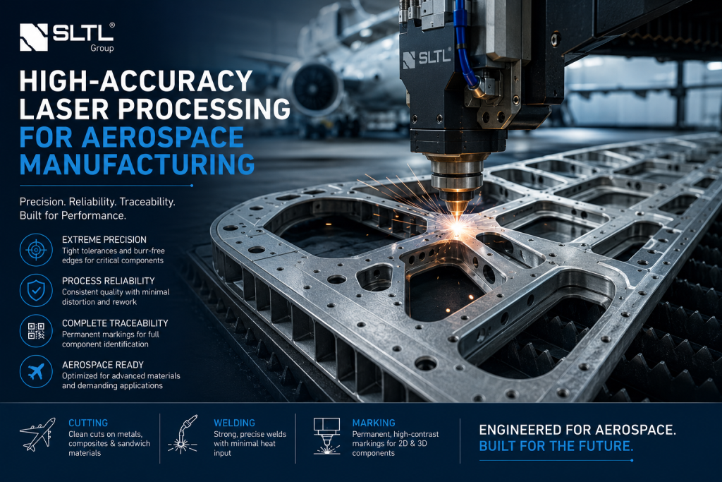
For the full technical detail on parameter selection and cut quality management for sandwiched panels, our article on How Laser Cutting Supports Sandwiched Aluminium Sheet Processing is the right starting point. Manufacturers at the machine selection stage will want to read our Laser Cutting Machine for Sandwiched Aluminium Sheets: Buyer Guide, which sets out the power, motion, and assist gas specifications that matter most for this application.
SLTL’s Future X — the most advanced laser cutting machine in the SLTL range — is equipped with all the advanced features needed to deliver this level of performance. With intelligent process control, high-brightness beam delivery, and fully integrated assist gas management, the Future X is built for the precision that aerospace sandwiched panel cutting demands. For high-volume or heavy-gauge panel programmes, the Infinity F1 high-power laser cutting machine delivers the raw cutting capacity to support large-scale aerospace production without compromising on edge quality or dimensional accuracy. For manufacturers looking to increase productivity at a more accessible investment level, the IntegreX is SLTL’s most affordable laser cutting machine — designed to bring efficiency and repeatability to aerospace cutting operations where capital cost is a constraint.
Composite Material Cutting
CFRP, GFRP, and aramid composites cannot be cut reliably by conventional contact methods at the tolerances aerospace production demands. Laser cutting — specifically ultrashort pulse laser technology — delivers the cold ablation mechanism that these materials require: energy delivered in pulses so short that the surrounding material has no time to absorb heat, resulting in minimal HAZ and clean, delamination-free cut edges.
Our article on Why Composite Material Cutting Needs Contactless Laser Technology covers the cutting mechanisms, HAZ management strategies, and material-specific requirements for CFRP, aramid, and hybrid composite structures in detail — essential reading before specifying a laser cutting system for composite work.
Tube Laser Cutting for Aerospace Frames
Aerospace frame structures — from commercial aircraft fuselage frames and floor beams to UAV chassis and satellite support brackets — are built from tubular and profiled sections that require precise end profiles, cope cuts, and access holes before assembly. Tube laser cutting systems process round, square, rectangular, and custom profile sections in a single setup, cutting complex weld-prep geometries and hole patterns with dimensional accuracy of ±0.1 mm or better.
This precision eliminates the fit-up variation that otherwise requires hand-fitting and shimming at assembly — directly reducing assembly time and improving joint quality for welded aerospace structures.
For a detailed look at how tube laser cutting supports aerospace frame manufacturing across commercial, defence, and space applications, our article on Tube Laser Cutting for Aerospace Frames and Support Structures covers the full picture. Manufacturers evaluating specific systems will find the Tube Laser Cutting Machine for Aerospace Component Manufacturers guide essential for understanding the axis configurations, chuck capacity, and automation features that define a capable aerospace tube cutting platform.
SLTL’s X5 3D laser cutting machine extends laser cutting capability to complex three-dimensional components and profiles, enabling aerospace manufacturers to cut curved tube sections, formed sheet metal parts, and 3D trimmed composite mouldings in a single operation — without fixturing compromises or multiple setups.
Laser Cutting vs CNC Routing
Both laser cutting and CNC routing are used in aerospace composite and sheet metal processing. The right choice depends on material type, thickness, required edge quality, batch size, and investment parameters. For thin composite sheet and aluminium sheet, laser cutting is almost always preferred — burr-free edges, no tool wear, faster cycle times, and no contact forces. For thick composite sections above 10–12 mm, CNC routing may still be preferred where laser HAZ becomes a limiting factor. Many aerospace manufacturers operate both technologies, with laser handling thin sheet and composite trimming, and routing handling thick composite cutting.
Our full process comparison — Laser Cutting vs CNC Routing for Aerospace Sheet and Composite Parts — provides objective, material-by-material guidance for production planners evaluating this decision.
Laser Welding for Aerospace: Precision Joining of Lightweight Structures
The Lightweighting Challenge and Why It Changes Welding
Every kilogram removed from an aircraft structure translates directly to reduced fuel burn and extended range. The drive for lightweighting across commercial aviation, military platforms, UAVs, and spacecraft has produced structures built from thinner sections, lower-density alloys, and hybrid material combinations that demand a welding process with exceptional heat control and dimensional precision.
Conventional TIG welding delivers high-quality joints on standard section thicknesses, but its relatively wide heat-affected zone (HAZ), manual sensitivity, and slower travel speeds make it increasingly unsuitable as sections become thinner and materials become more heat-sensitive. Laser welding concentrates energy in a focal spot of 0.3 to 0.6 mm diameter for precision aerospace applications, producing a narrow, deep weld bead with a HAZ up to five times smaller than TIG on the same material.
For age-hardened aluminium alloys — the most common structural alloys in commercial airframes — a large HAZ softens the material in the joint vicinity, reducing the effective load-bearing capacity of the structure. Laser welding’s minimal HAZ preserves base material strength, enabling lighter, more efficient structural design without joint reinforcement penalties.
Our article on How Laser Welding Supports Lightweight Aerospace Components covers the engineering principles behind laser welding’s HAZ advantage, with application examples for thin-section titanium, aluminium-lithium alloys, and dissimilar-metal aerospace joints.
SLTL’s Nova laser welding machine — available from 200 to 500W and fully customisable — is designed for the precision welding requirements of aerospace structural and component assembly. Its fully customised configuration options allow it to be specified exactly for the material, section thickness, joint geometry, and inert gas shielding requirements of each aerospace application. For lighter-duty precision joining applications and special materials, SLTL’s ENZO laser welding machine — up to 200W, with specialist capability for gold welding and fine jewellery-grade joining — brings a level of pulse precision that also serves certain aerospace sensor and instrument applications. For on-site or large-structure welding where the workpiece cannot be brought to a fixed welding cell, SLTL’s Hertz handheld laser welding machine provides the same laser joining quality in a portable format — with obvious applications for maintenance, repair, and overhaul (MRO) operations in aerospace.
Weld Quality Certification and Process Monitoring
Aerospace welding quality is governed by a framework of standards — AWS D17.1, EN 4179, and NADCAP welding requirements — that mandate process qualification, ongoing production monitoring, and comprehensive documentation for every weld produced. For laser welding in a certified aerospace environment, the machine must not only make high-quality welds; it must prove it does so consistently, on every part, with a documented audit trail.
Modern laser welding systems used in aerospace incorporate optical coherence tomography (OCT) for real-time weld depth measurement, photodiode plasma monitoring to detect process instability mid-weld, camera-based melt pool monitoring for weld pool geometry control, and direct integration with NDT inspection systems for post-weld X-ray or ultrasonic testing. These monitoring layers enable closed-loop process control and generate the parameter records and alarm logs that NADCAP quality auditors require.
Our article on Laser Welding Quality Checks for Aerospace Component Suppliers covers the full inspection and monitoring framework in detail, including the specific checks and documentation requirements that apply to NADCAP-compliant laser welding operations. Manufacturers specifying a complete laser welding system will find the Laser Welding Machine for Aerospace Precision Assemblies guide covers the machine architecture, beam delivery options, and certification support features that matter most in a certified aerospace environment.
Laser Marking for Aerospace: Permanent Identification and Regulatory Traceability
Why Laser Marking is a Regulatory Requirement, Not an Option
Every flight-critical aerospace component must carry permanent, legible identification that enables it to be traced back through every stage of its manufacturing and certification history. This is not a quality best practice — it is a regulatory mandate under AS9100, EASA Part 21, FAA regulations, and IAQG standards. It supports airworthiness investigation when components fail in service, enables counterfeit part detection across the supply chain, protects maintenance record integrity throughout a component’s service life, and satisfies country-of-origin and classification marking requirements for international shipment.
Laser marking delivers the permanent, tamper-resistant identification these requirements demand. A laser mark cannot be removed, reapplied, or duplicated without physically damaging the component surface — something that even a cursory inspection would reveal. Unlike ink-based printing, which fades under thermal cycling, UV exposure, and chemical cleaning, laser marks remain readable throughout a component’s entire service life.
For a comprehensive guide to what the regulatory framework actually requires and how laser marking systems meet those requirements across different aerospace supply chain tiers, our article on Laser Marking for Aerospace Traceability: What Manufacturers Should Know covers the full landscape.
What Gets Marked: Content and Formats
Aerospace laser marking covers several categories of content. Part identification markings include part numbers, serial numbers, revision levels, and lot/batch codes — typically in human-readable format and encoded in 2D Data Matrix barcodes for automated scanning in MRO and assembly. Regulatory and certification markings include CAGE codes, country of origin, material specification references, and approval marks, all of which must meet specific font size, contrast, and permanence requirements. Date and traceability codes encode manufacturing date, inspection date, or composite cure date for maintenance interval and shelf-life management purposes.
Marking Technologies for Aerospace Applications
Different aerospace applications require different laser marking mechanisms. Annealing marking on stainless steel and titanium creates a flush colour change through controlled oxidation — no material is removed — making it ideal for fatigue-critical components where surface stress risers are unacceptable. Ablation marking removes a thin surface layer or coating to expose a contrasting substrate, and is widely used for anodised aluminium aerospace parts. Deep engraving removes material to a controlled depth of 0.05 to 0.3 mm, creating marks that remain readable after painting, coating, or light abrasion — the standard for identification plates and components in harsh environments.
Colour Marking vs Black Marking
One of the more nuanced specification decisions in aerospace laser marking is the choice between colour marking and black marking for identification plates, control panel labels, and assembly zone markers. Black marking — produced by annealing or ablation — delivers high contrast and excellent readability under all lighting conditions and is the standard for functional part identification markings. Colour marking — achievable on titanium and stainless steel through controlled annealing parameter variation — produces marks in gold, blue, purple, and other tones, and is increasingly applied for colour-coded zone identification on multi-component assemblies and branded aerospace identification plates. Our article on Color Marking vs Black Marking for Aerospace Identification Plates covers the material-specific marking colour capabilities, contrast and readability requirements, and the use cases where each approach is most appropriate.
3D Marking for Curved Aerospace Components
Standard flat-field laser marking systems are well-suited for flat identification plates and planar part surfaces. But many aerospace components that require traceability marking are not flat — engine housings, turbine blade platforms, structural fittings, and bracket assemblies all present curved or compound-curved surfaces that defeat the focal plane of a fixed flat-field system.
As the laser beam moves away from the focal plane on a curved surface, the spot size increases and mark quality degrades — producing inconsistent mark depth, poor contrast, and potentially unreadable 2D codes at the edges of the marking field. For parts with significant surface curvature, this is not acceptable under aerospace traceability requirements.
Special-purpose marking (SPM) systems address this with 3D scanning optics that map the part surface geometry and adjust the focal plane dynamically as the marking head traverses the part — delivering consistent mark quality across compound-curved surfaces without repositioning.
Our article on the SPM Laser Marking Machine for Aerospace 2D and 3D Jobs explains how these systems work in practice, what the 3D scanning optics deliver in terms of marking consistency, and where they are being applied across aerospace engine component and structural part marking programmes.
Choosing the Right Laser Marking Machine
Selecting a laser marking machine for aerospace is a specification decision that carries long-term production implications. The range of available systems — fibre laser for metals, CO₂ for non-metallics, UV for heat-sensitive materials and fine detail, DPSS for certain specialist applications — each deliver different performance characteristics across the aerospace material mix.
Key selection criteria include laser wavelength matched to the primary material family, pulse duration and peak power for the required marking mechanism (annealing, ablation, or deep engraving), marking field size to accommodate the part range, 3D marking capability for curved components, and software capability for AS9100-compliant variable data marking with ERP and MES integration.
Our selection guide — How to Choose a Laser Marking Machine for Aerospace Parts — walks through all of these criteria with aerospace production context built in. If you want to compare specific systems against each other, our reviewed comparison — Best Laser Marking Machine for Aerospace Traceability — covers the leading fibre, UV, and DPSS platforms currently used in aerospace traceability applications.
What to Look for in a Laser Machine for Aerospace Manufacturing
Whether you are evaluating a laser cutting machine, a laser welding machine, or a laser marking machine for aerospace production, four requirements apply universally.
Process qualification compatibility. The machine must generate the parameter documentation required for AS9100, NADCAP, or customer-specific process qualification — including parameter recording for every production run, traceability of consumables, and the statistical process data needed to demonstrate process capability. A machine that cannot produce this data is not suitable for a certified aerospace environment, regardless of its raw cutting or welding performance.
Repeatability and drift management. Laser power output, beam quality, and focus position all drift over time as optical components age and thermal conditions change. Aerospace-grade machines must monitor these parameters continuously and compensate for drift automatically. A machine that holds its specification on day one but drifts outside it six months into production is not a reliable aerospace solution.
Material range coverage. Define the full range of materials the machine will need to process — not just the current production mix, but the next three to five years of programme requirements. Aerospace supply chains regularly introduce new alloys and composite specifications, and a machine that cannot accommodate them may require costly replacement sooner than expected.
Quality system integration. Data output from the laser machine — process parameters, alarm events, operator identity records, per-part timestamps — must interface directly with the facility’s quality management system. Manual paper-based parameter recording is increasingly unacceptable in Tier 1 and Tier 2 aerospace environments and will not support a NADCAP audit without significant supplementary process controls.
SLTL Laser Solutions for Aerospace Manufacturing
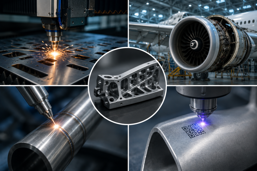
SLTL’s range of laser machines for aerospace manufacturing covers the full spectrum of cutting, welding, and marking requirements across the industry.
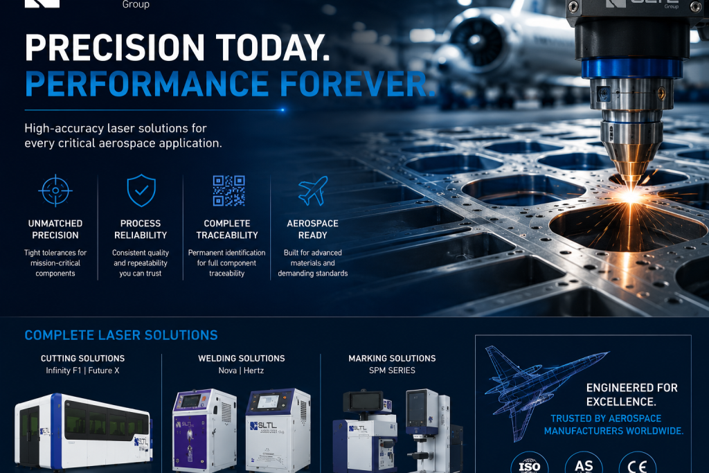
For laser cutting, the Future X is SLTL’s most advanced cutting platform — equipped with intelligent process control, high-brightness beam delivery, and all the advanced features needed to hold aerospace tolerances across aluminium sheet, sandwiched panels, titanium, and composite materials. The Infinity F1 high-power laser cutting machine is built for heavy-duty, high-volume aerospace production where raw cutting capacity and continuous uptime are the primary requirements. The IntegreX is SLTL’s most affordable laser cutting machine, designed to bring laser precision and repeatability to aerospace manufacturers who need to increase productivity and efficiency without a high-end investment. And the X5 3D laser cutting machine opens up 3D cutting capability for formed components, curved profiles, and trimmed composite mouldings — applications that flat-bed cutting machines simply cannot address.
For laser welding, the Nova (200–500W, fully customised) is SLTL’s primary platform for structural and precision aerospace welding, with full customisation of beam delivery, shielding, monitoring, and motion to match the specific requirements of each aerospace programme. The ENZO (up to 200W) brings fine-pulse precision for instrument and sensor component welding, while the Hertz handheld laser welding machine extends laser joining capability to field repair, on-aircraft MRO, and large-structure welding where the workpiece cannot be brought to a fixed cell.
For laser marking, SLTL’s SPM (Special-Purpose Marking) systems address the full range of aerospace identification requirements — from flat identification plate marking through to 2D Data Matrix coding on curved structural components — with 3D scanning optics for consistent mark quality across compound surfaces.
Conclusion: The Case for High-Accuracy Laser Processing in Aerospace
The adoption of laser machines for aerospace manufacturing is not a technology trend. It is a rational response to the material, tolerance, traceability, and certification demands that define one of the most regulated industries in the world.
Laser cutting eliminates the contact-force limitations of CNC routing for composite and thin-metal processing, delivers the dimensional accuracy that structural aerospace components require, and enables precise processing of tube and profile sections for lightweight frame assemblies. Laser welding provides the heat-input control that lightweight alloy structures demand, the process consistency that NADCAP certification requires, and the monitoring integration that closed-loop quality systems depend on. Laser marking delivers permanent, tamper-resistant identification that satisfies regulatory traceability requirements from Tier 3 component suppliers through to OEM final assembly.
For aerospace manufacturers evaluating laser processing capability, the starting point is matching machine specification to the specific material, tolerance, throughput, and quality system requirements of your production programme. SLTL’s range of laser cutting, welding, and marking solutions is designed to support that match — with the application expertise and ongoing support to back it through the full operational life of the installation.
Ready to discuss laser processing for your aerospace manufacturing application? Contact the SLTL aerospace laser team to discuss your production requirements, or explore the SLTL range of laser cutting, laser welding, and laser marking machines for aerospace.
Frequently Asked Questions: Laser Machines for Aerospace Manufacturing
These are the questions aerospace manufacturers ask us most often — answered directly, so you can move from evaluation to decision with confidence.
Q1. Are laser cutting machines accurate enough to meet aerospace tolerances?
Yes. Modern fibre laser cutting machines achieve positional accuracy of ±0.05 mm or better with no tool wear to introduce drift across a batch. For structural components, precision brackets, and thin-section sheet metal, laser cutting consistently meets aerospace engineering drawing requirements without secondary correction operations.
Q2. Can a laser cutting machine process both metal and composite materials on the same platform?
It depends on the laser type. Fibre laser systems like the SLTL Future X and Infinity F1 are optimised for metals. Composites such as CFRP and aramid require different laser parameters and often a different source. Many manufacturers run separate platforms for each. Read Why Composite Material Cutting Needs Contactless Laser Technology for material-specific guidance.
Q3. What is the difference between laser welding and TIG welding for aerospace structural joints?
Laser welding produces a heat-affected zone up to five times smaller than TIG on the same material, preserving base material strength in lightweight alloy joints. It is faster, more repeatable, and generates the process monitoring data that NADCAP and AS9100 require. See How Laser Welding Supports Lightweight Aerospace Components for the full engineering comparison.
Q4. How does laser marking meet aerospace traceability and regulatory requirements?
Laser marks are permanent, tamper-resistant, and readable through paint cycles, thermal cycling, and solvent cleaning — meeting AS9100, EASA Part 21, and FAA traceability mandates. Laser systems also log per-part parameters — power, timestamp, operator ID — forming part of the certification record. See Laser Marking for Aerospace Traceability: What Manufacturers Should Know.
Q5. What is the difference between 2D and 3D laser marking, and when does an aerospace manufacturer need 3D capability?
2D systems mark flat surfaces accurately. On curved components — engine housings, structural fittings, bracket assemblies — the laser defocuses away from the focal plane, degrading mark quality. 3D systems like SLTL’s SPM platform use dynamic focus control to maintain consistent mark depth across compound-curved surfaces. See SPM Laser Marking Machine for Aerospace 2D and 3D Jobs.
Q6. How do I know which SLTL laser machine is right for my aerospace application?
Match the machine to your material, volume, and quality requirements. Future X for advanced cutting performance; Infinity F1 for high-volume heavy-duty production; IntegreX for productivity at accessible investment; X5 for 3D cutting. For welding: Nova for structural work, ENZO for fine-pulse precision, Hertz for handheld MRO applications. Contact SLTL to confirm the right fit.
Q7. Can SLTL laser machines support NADCAP qualification for welding and marking?
Yes. SLTL’s Nova welding machine logs laser power, travel speed, focus position, and shielding gas flow per weld, with process monitoring integration for melt pool and plasma data. Marking systems generate per-part parameter records. NADCAP qualification is process-level — SLTL provides the machine capability and documentation support to make it achievable. See Laser Welding Quality Checks for Aerospace Component Suppliers.
Q8. What is the typical lead time and support structure for SLTL laser machines in aerospace production environments?
Lead times vary by machine type and location — SLTL’s team will confirm specifics based on your configuration. All SLTL aerospace machines are backed by application-level support: process development, parameter optimisation, operator training, and ongoing technical assistance throughout the machine’s operational life. Contact the SLTL team to discuss your requirements.